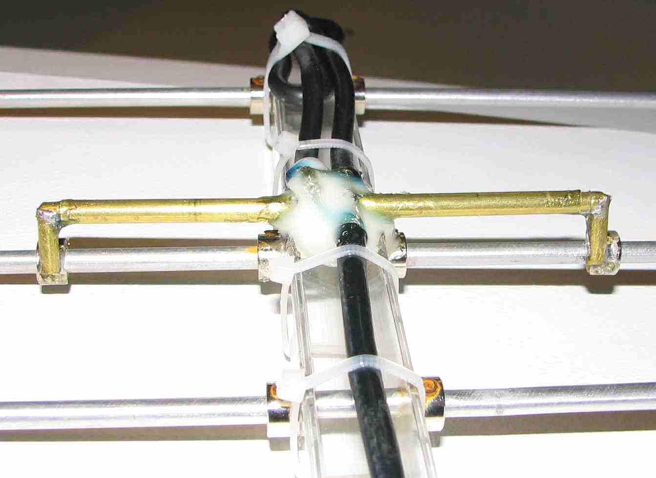
7 Element 440Mhz Yagi

| Element | Length | Position |
| Inches | Inches |
| Reflector | 13.750 | 0.0000 |
| Driven | 13.250 | 3.0625 |
| Director 1 | 11.875 | 4.8750 |
| Director 2 | 11.500 | 10.8750 |
| Director 3 | 11.500 | 16.8750 |
| Director 4 | 11.375 | 22.8750 |
| Director 5 | 10.875 | 29.5000 |
The T-Match connects to the driven element 3.25 inches from the center on each side with a separation of 0.375 inches center to center. The elements are made out of 3/16th inch diameter aluminum rod. The T-Match is made out of brass tubing, two sizes that telescope (the larger size is 3/16th). The hardware that holds the elements in place are nickel plated brass with a set screw. (You might want to replace the set screws with stainless if you can find them.)
I got these at the local hobby shop, they are often used to hold wheels on model airplanes. I used two of these in construction of the T-Match, I ground a chunk out of each one so that I had a reasonable surface to solder the brass tubing to. The telescoping tubing allows for adjustment of the T-Match for lowest SWR. The boom is just a piece of 1 inch square acrylic tube, but I don't think it will hold up to the sun very well. You might want to get something that is UV resistant (usually black). I put a very slight chamfer on the ends of the elements, not much more than is needed to de-bur the ends.
Under the glue at the center of the T-Match is the feed point. The piece of coax that is coiled up by the reflector is one half electrical wavelength at the operating frequency (I think I chose 440 MHz).This piece of coax makes a 4 to 1 balun. Since the feed point impedance is 200 ohms the balun transforms it to 50 ohms. The center of each end of this piece of coax is connected to each side of the T-Match
and the shield ends are connected together along with the shield of the coax used to feed the antenna. The center conductor of the feed line is connected to one side of the T-Match (either one) along with the coax balun.
The model shows a gain of more than 16.8 dbi. The front to back is almost 40 db with all other lobes more than 20 db down. The SWR is incredibly flat across the whole band, 1.13 at 430 MHz 1.022 at 437 MHz and 1.25 at 450 MHz. All this is according to the model I did in EZNEC. A friend (Don WA6GXB SK) and I took this to a large empty field to test it. To get a signal that did not peg my S-meter I had to turn on the attenuator (10db) and move about a mile away. The transmitter power was only 0.05 watts. We did not have any calibrated equipment to make measurements with but this antenna worked very well. I gave it to Don because I plan on making one on an eight foot boom instead of just 2.5 feet. Don is now a silent key and I miss him very much.


