

|

|
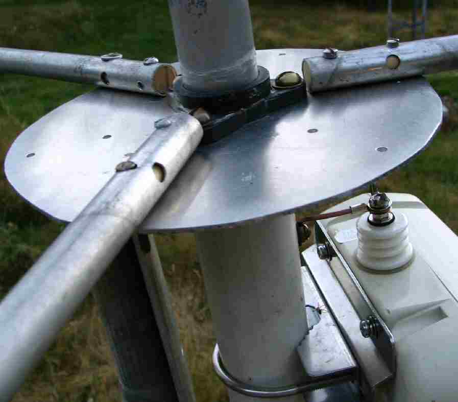
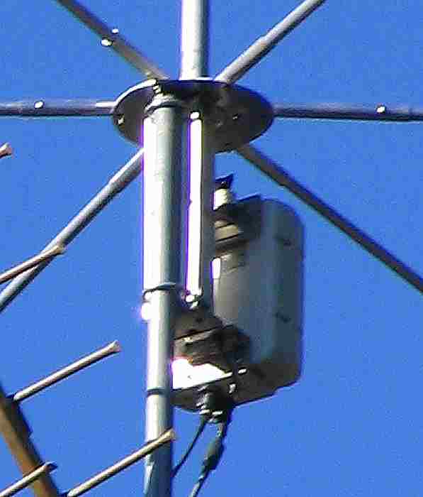
| These are close up photos of the base of the antenna. The one on the left is during early testing. What I did was disassemble an old C.B. antenna (thanks neighbor). I discarded most of the guts and replaced them with PVC pipe. I cut three pieces, two that just fit where the old coil housing was removed. In one of these I cut a slot down the side so that I could squeeze it inside the first tube so that I would have a double thickness pipe. With a little filing and sanding this was just the right size to accept the bottom portion of the vertical radiator. The third piece of pipe was the same outer diameter as the vertical radiator, I cut this about half as long as the first two pieces and inserted it in the bottom of the other two pipe sections to keep the radiator from sliding too far in. In the bottom of the radiator element I pushed in a piece of steel that was wrapped in aluminum sheet to shim it to the correct diameter. | I cut a circle out of a piece of aluminum and drilled a large hole in the center to accept the plastic insulator for the vertical section and drilled mounting holes for the insulator and radial mounting hardware. In the left picture you can see that wooden dowels and whatever hardware was handy was used to attach the radials. In the final version the wood dowels were replaced with Delrin dowels and stainless hardware was used. A sleeve of aluminum tube was placed over the first eight inches of each of the six radials to add strength. These can be seen in the picture on the right. About an inch up from the bottom of the vertical element I drilled and tapped a hole through the PVC and aluminum and into the steel so that I could connect the output of the AH-4 antenna tuner to the radiator. I connected the ground for the tuner to the aluminum mounting bracket which also gives an electrical connection to the radials. |